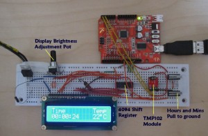
So, for our first trick we thought we’d try and conjour up a thermometer, and then we added a clock as well – just for good measure.
Pretty much all the parts came from Cool Components or Maplin. I got a cheap 2 line display on sale which was the starting point, then wondered what we could create to educate…
The LCD interface is through 3 wires and a 4094 shift register. I’ve taken the example 3 wire LCD code from the arduino playground at http://www.arduino.cc/playground/Code/LCD3wires and modified and extended it a little to provide some positioning functions and improve the number drawing code.
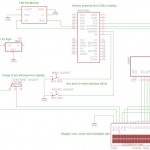
Schematic and Breadboard

Explanation
The thermometer functionality comes from TMP102 module which is connected through an I2C bus, implemented with the Wired library. The I2C interface is very easy to use, call
Wired.begin
in setup() to initialise it, then its a simple case of reading the latest temperature values. The addressing here assumes that the ADD0 line on the module is pulled to ground:
// Temperature module commands and registers
int  TMP_RD = 0x91;
int  TMP_WR = 0x90; //Assume ADR0 is tied to VCC
int  TEMP_REG = 0x00;
int  TEMP_ADDR = 0b1001000;

int ReadTemperature()
{
 int  val_h = 0;
 int  val_l = 0;

 Wire.requestFrom(TEMP_ADDR, 2);
 val_h = Wire.receive();
 val_l = Wire.receive();

  //  calc temp in C
 int tempint = ((val_h << 8 ) | val_l) >> 4;      // combine and shift
 float tempflt = float( tempint ) * .0625; // calculate actual temperature per chip doc
 return int(tempflt);
}
The clock works by using the millis() function to establish a base time and a corresponding millisecond count – then we can update the display anytime by calculating the time since a known base. If the millis() wraps we adjust the base to the last known good value and go from that. There will be a little bit of creep there but only once every 1193 hours ish… Clock adjustment is through two switches which pull digital inputs to ground – if they are low we increment the base Hours or Minutes value depending which button is pressed. The internal pull up resistors are used to ensure the inputs don’t float about when the button isn’t pressed, here’s an extract:
// set up input
 pinMode(HOURS,INPUT);
 digitalWrite(HOURS, HIGH);       // turn on pullup resistor

//Adjust the clock
 boolean    bRet = false;         // was an adjustment made
 if (digitalRead(HOURS) == LOW)   // read the input switch
 {
   iBaseH++;
   if (iBaseH > 23)
   {
     iBaseH = 0;
   }
   bRet = true;
 }
After that all you need to do is just get data for the temperature or the time and then call the display routines.
The code for the whole thing is here.